Hi guys,
In this post i'm going to explain in depth how to control robot car using Nodemcu and blynk.
We are going to program nodemcu there is a seperate ide but in this project we are programing it using arduino ide, hence the ide thinks that we are programing for arduino so before programming we have to know about the pinouts of nodemcu corresponding to arduino.Below is the image through which you can understand the pinout .
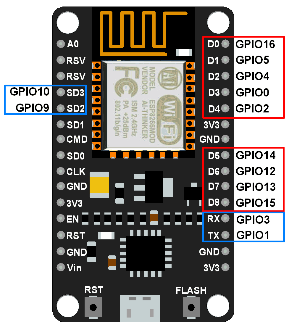
Eg: If we use D0 pin of Nodemcu as output ,we have to declare pin 16 as an output in arduino ide.
After knowing the pinouts now let us jump in to the hardware and coding section .
HARDWARE:
Things needed:


CODE:


In this post i'm going to explain in depth how to control robot car using Nodemcu and blynk.
We are going to program nodemcu there is a seperate ide but in this project we are programing it using arduino ide, hence the ide thinks that we are programing for arduino so before programming we have to know about the pinouts of nodemcu corresponding to arduino.Below is the image through which you can understand the pinout .
Eg: If we use D0 pin of Nodemcu as output ,we have to declare pin 16 as an output in arduino ide.
After knowing the pinouts now let us jump in to the hardware and coding section .
HARDWARE:
Things needed:
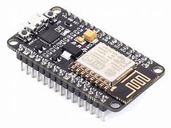
- 1 x Nodemcu
- 1 x L298N motor driver
- 2 x Bo motors
- 3 x wheels
- jumper wires
L298N MOTORDRIVER:

BO MOTORS:
JUMPER WIRES:

Now its time to connect all these connections :

Description

Getting to Know Your L298N Dual H-Bridge Motor Controller Module
An H-Bridge is a circuit that can drive a current in either polarity and be controlled by Pulse Width Modulation (PWM).
What is Pulse Width Modulation?
Pulse Width Modulation is a means in controlling the duration of an electronic pulse. Motors will last much longer and be more reliable if controlled through PWM.
Specifications:
- Double H bridge Driver Chip: L298N
- Logical voltage: 5V
- Drive voltage: 5V-35V
- Logical current: 0-36mA
- Drive current: 2A (MAX single bridge)
- Max power: 25W
Note: Built-in 5v power supply, when the driving voltage is 7v-35v. But i recommend you not to power up your microcontroller with on-board 5v power supply.
1:connect the bo motor to the motor driver as shown below
2: connect the motor driver to nodemcu as given below:
- GPIO2(D4)- IN3
- GPIO15(D8)-IN1
- GPIO0(D3)-IN4
- GPIO13(D7)-IN2
- GPIO14(D5)-Enb-A
- GPIO12(D6)-Enb-B
+12v - Positive terminal of the battery to be connected.
GND - Ground terminal of the battery to be connected.
+5v - +5v input (unnecessary if your power source is less than +7v to +9v, if the power source is greater than +9v to +35v then it can act as a 5v out)
Input Connections :
(Motor A)
ENA - Enables PWM signal for Motor A
IN1 - Enable Motor A
IN2 - Enable Motor A
(Motor B)
ENB - Enables PWM signal for Motor B
IN3: Enable Motor B
IN4: Enable Motor B
Note :
- Make sure you have all of your grounds connected together. (NodeMCU, Power Source, and Motor Driver)
- The PWM Pins are unnecessary if you do not want to control PWM features.
Software Requirements
- Arduino IDE
- The code is given below just paste the code in the arduino ide :
- select the nodemcu board and the correct com port
Click here to download the Ardunio code file directly
#include <ESP8266WiFi.h>
#include <BlynkSimpleEsp8266.h>
/* define L298N or L293D motor control pins */
int leftMotorForward = 2; /* GPIO2(D4) -> IN3 */
int rightMotorForward = 15; /* GPIO15(D8) -> IN1 */
int leftMotorBackward = 0; /* GPIO0(D3) -> IN4 */
int rightMotorBackward = 13; /* GPIO13(D7) -> IN2 */
int z;
/* define L298N or L293D enable pins */
int rightMotorENB = 14; /* GPIO14(D5) -> Motor-A Enable */
int leftMotorENB = 12; /* GPIO12(D6) -> Motor-B Enable */
// You should get Auth Token in the Blynk App.
// Go to the Project Settings (nut icon).
// Use your own WiFi settings
char auth[] = "**********";
char ssid[] = "type your network name here ";
char pass[] = "type your network password here";
// neutral zone settings for x and y
// joystick must move outside these boundary numbers to activate the motors
// makes it a little easier to control the wifi car
int minRange = 312;
int maxRange = 712;
// analog speeds from 0 (lowest) - 1023 (highest)
// 3 speeds used -- 0 (noSpeed), 350 (minSpeed), 850 (maxSpeed).
// use whatever speeds you want...too fast made it a pain in the ass to control
int minSpeed = 450;
int maxSpeed = 1023;
int noSpeed = 0;
void moveControl(int x, int y)
{
// movement logic
// move forward
// y je vetsi jak maxrange a současně x je vetsi jak minRange a současne mensi jak max range
if(y >= maxRange && x >= minRange && x <= maxRange) //zataci R
{
analogWrite(leftMotorENB,z);
analogWrite(rightMotorENB,z);
digitalWrite(leftMotorForward,HIGH);
digitalWrite(rightMotorForward,HIGH);
digitalWrite(leftMotorBackward,LOW);
digitalWrite(rightMotorBackward,LOW);
}
//MOVE FORWARD RIGHT
else if(x <= minRange && y >= maxRange )
{
digitalWrite(leftMotorENB,maxSpeed);
digitalWrite(rightMotorENB,minSpeed);
digitalWrite(leftMotorForward,HIGH);
digitalWrite(rightMotorForward,HIGH);
digitalWrite(rightMotorBackward,LOW);
digitalWrite(leftMotorBackward,LOW);
}
// move right
else if(x >= maxRange && y >= minRange && y<=maxRange) //zataci R
{ analogWrite(leftMotorENB,z);
analogWrite(rightMotorENB,z);
digitalWrite(leftMotorForward,HIGH);
digitalWrite(rightMotorForward,LOW);
digitalWrite(rightMotorBackward,HIGH);
digitalWrite(leftMotorBackward,LOW);
}
// move forward LEFT
else if(x <= minRange && y >= maxRange )
{
digitalWrite(leftMotorENB,minSpeed);
digitalWrite(rightMotorENB,maxSpeed);
digitalWrite(leftMotorForward,HIGH);
digitalWrite(rightMotorForward,HIGH);
digitalWrite(rightMotorBackward,LOW);
digitalWrite(leftMotorBackward,LOW);
}
// moveleft
else if(x <= minRange && y >= minRange && y <= maxRange)
{
analogWrite(leftMotorENB,z);
analogWrite(rightMotorENB,z);
digitalWrite(leftMotorForward,LOW);
digitalWrite(rightMotorForward,HIGH);
digitalWrite(rightMotorBackward,LOW);
digitalWrite(leftMotorBackward,HIGH);
}
// neutral zone
else if(y < maxRange && y > minRange && x < maxRange && x > minRange)
{
digitalWrite(leftMotorENB,LOW);
digitalWrite(rightMotorENB,LOW);
digitalWrite(leftMotorForward,LOW);
digitalWrite(leftMotorBackward,LOW);
digitalWrite(rightMotorForward,LOW);
digitalWrite(rightMotorBackward,LOW);
}
// move back
else if(y <= minRange && x >= minRange && x <= maxRange)
{
analogWrite(leftMotorENB,z);
analogWrite(rightMotorENB,z);
digitalWrite(leftMotorBackward,HIGH);
digitalWrite(rightMotorBackward,HIGH);
digitalWrite(leftMotorForward,LOW);
digitalWrite(rightMotorForward,LOW);
}
// move back and right
else if(y <= minRange && x <= minRange)
{
digitalWrite(leftMotorENB,maxSpeed);
digitalWrite(rightMotorENB,minSpeed);
digitalWrite(leftMotorForward,LOW);
digitalWrite(rightMotorForward,LOW);
digitalWrite(rightMotorBackward,HIGH);
digitalWrite(leftMotorBackward,HIGH);
}
// move back and left
else if(y <= minRange && x >= maxRange)
{
digitalWrite(leftMotorENB,minSpeed);
digitalWrite(rightMotorENB,maxSpeed);
digitalWrite(leftMotorForward,LOW);
digitalWrite(rightMotorForward,LOW);
digitalWrite(rightMotorBackward,HIGH);
digitalWrite(leftMotorBackward,HIGH);
}
}
void setup()
{
// initial settings for motors off and direction forward
pinMode(leftMotorForward, OUTPUT);
pinMode(rightMotorForward, OUTPUT);
pinMode(leftMotorBackward, OUTPUT);
pinMode(rightMotorBackward, OUTPUT);
/* initialize motor enable pins as output */
pinMode(leftMotorENB, OUTPUT);
pinMode(rightMotorENB, OUTPUT);
Blynk.begin(auth, ssid, pass);
}
void loop()
{
Blynk.run();
}
BLYNK_WRITE(V1)
{
int x = param[0].asInt();
int y = param[1].asInt();
moveControl(x,y);
}
BLYNK_WRITE(V2)
{
z = param[0].asInt();
}
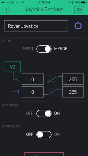
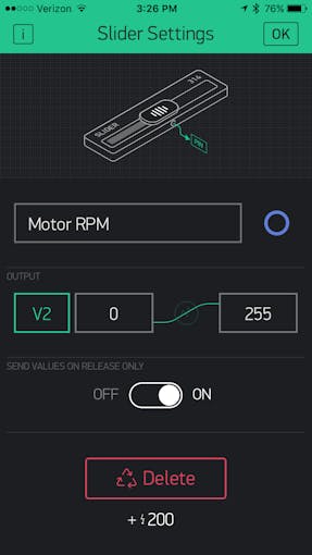
SETTING BLYNK APP :
Change the pin to V1 and value from 0 to 1023 in both the cases.
Change the pin to V2 and value from 0 to 1023 .
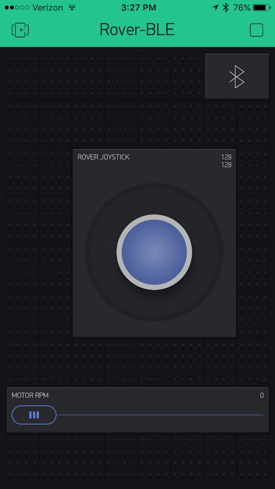
Thats it the project is complete you can now control the car using blynk joystick.
- Turn on your mobile hotspot, wait till the nodemcu connects to the mobile hotspot and ""walla! "now you can control the car using your mobile via blynk .
Hello manitesla
ReplyDelete