Tuesday, July 9, 2019

How to make line following vacuum cleaning robot


Introduction

Hi guys i'm Manikant savadatti , today we are going to build a vaccum cleaning robot using house old items. I had built a robot car in my last instructable ,i wanted to upgrade it and build something which will help my mom in her house cleaning . Hence , I thought of making a vaccum cleaning robot . To clean the house we have to map the house using algorithms and AI but as this is a project in which we are going to build from scratch we will be making a line following robot which cleans the specific area ( place where track is present).In the next project i'm going to teach you guys how to map the room . 

Supplies:

  1. Cardboard   

  1. Glue
  1. Ir sensor ( watch my previous blog to build it )
  1. Nodemcu / Arduino
  1. Motor driver

  1. jumper wires


  1. Bo motors

  1. Propellor / impellor


Step 1: Hardware

Making robot chasi :
  • Take a piece of cardboard and cut it to make a rectagular shape ( choose breadth and length size of cardboard according to your requirements )


  • Connect  the Bo motors to all the four corners of the rectangle board using srews

  • Connect the motors to the motor driver as shown 
Picture of Hardware
  • Connect the motor driver to the Nodemcu /Arduino as given in the code
  • If you use the connection as given above in the diagram you have to make few changes in the code
  • Hence to avoid this connect the arduino and motor driver as i have given in the code
  • Last step is to connect the ir sensor to microcontroller
  • Connect the positive and negative terminal of sensor to the +5 and gnd of arduino or motor driver
  • Connect the signal pins of sensor to pin 6 and 7 of arduino


Step 2: Making Vaccum Turbine / Dust Collector

Making vaccum turbine: 
  • Take any plastic cup or any cylindrical tube or take an old bottle and cut it .


  • Make hole and place the motor above it as shown in image

  • Fix propellor or impellor to it from inside of the cylinder
  • Make a hole at the edge of cylindrical cup to let the air out 
  • Make a hole in robot chasi and place the turbine above the hole such that you can see propellor from the bottom of the car
  • Place a wire mesh or net in front of propellor or at the output of the turbine


  • Take any cylindrical pipe and wrap sponge or any brush type material to make dust collecting roller
  • I have made the dust collecting brush from a old glue bottle and a vessel cleaning sponge
  • You can rotate the roller using a motor by connecting motor to the gear of roller
  • Or you can leave the roller as it is because the roller rotates automatically due to friction with the floor, as the robot moves forward


  • The dust gets collected in the box 
  • You can watch the above images to get better idea of it .

Step 3: Software :

I have written lot of comments in the code so that even a beginer can understand the code . Just upload the code into Nodemcu / Arduino .You can view my previous instructable to know about how to use nodemcu using arduino ide .If you want to control the robot car using mobile instead of line following visit this link( click here) just paste the code of that project instead of the code given below
Code working:
  • When ir sensor detects the floor it will send the signal 1 and when it detects black line it sends 0 to the arduino/nodemcu .
  • When the left ir sensor detects the black strip robot will move right
  • When the right ir sensor detects black strip robot will move left
  • When both the sensors detect black strip the robot will stop
  • The main logic is the robot tries to move such that the sensors only detect the floor and the track should be present in b/w the sensors.
     
           Click here to download the direct Arduino code  file


Wednesday, June 26, 2019

How to make ir sensor/proximity sensor/obstacle sensor

Hi  guys i'm Manitesla let' s start our project.
In this project i'm going to explain how to make your own ir sensor and how to use it using arduino and without arduino.


components requires:
  • 1 x Ir transmitter ,receiver


  • 1 x 10k resister

  • 1 x 100ohm resistor


Hardware connection:


  • connect the ir leds has shown in the figure


  • Connect the anode of ir transmitter to 100 ohm resisitor
  • Connect the negative of ir receiver to 10k resistor
  • Connect both the ends of 10k and 100ohm resistor (this is the +ve pin , connect it to 5v)
  • Connect the anode and cathode of ir receiver and ir transmitter together(this is the -ve pin, connect it to ground)
  • Connect an  another wire to anode of receiver  (this is the signal pin)
  • You can identify the anode and cathode of led by lookind at the pins , the longer pin is anode and shorter is cathode
  • You can also identify anode and cathode by looking at the edge of led, the flat edge of led id cathode.
  • Iyou do not find 100 ohm resistor as i did you can use any other resistor nearer to 100 ohm.
  • Ir sensor module is ready .
obstacle sensor circuit without arduino:


Connect the components as shown in the above circuit to make obstacle sensor .

  • Take the ir sensor which we built above , connect the signal pin of ir led to base of 2n222a/ bc547 transistor(add resistor to base if required)
  • Connect emitter of transistor to ground and also connect gnd pin of ir sensor to ground
  • Connect collector of transistor to cathode of led  
  • Connect the  anode of led ,and ir sensor to 5v
obstacle detector using arduino:

  1. Take your arduino board and ir transmitter and receiver.


2. Connect transmitter anode to 100 ohm and to 5v and connect cathode to gnd
3.
  • Connect anode of receiver to cathode of transmitter
  • Connect 10k resistor to ir receiver anode 
  • Connect both the resistor ends to 5v
  • Connect the signal pin taken from receiver to A5 on arduino.


 *Open the arduino ide and paste the code given below and upload it to the uno board.


1. Paste the given code in arduino ide


                                         Click here to download the direct Arduino code file


code:

Wednesday, June 19, 2019

Wifi controlled robot using Nodemcu and blynk joystick

Hi guys,
In this post i'm going to explain in depth how to control robot car using Nodemcu and blynk.
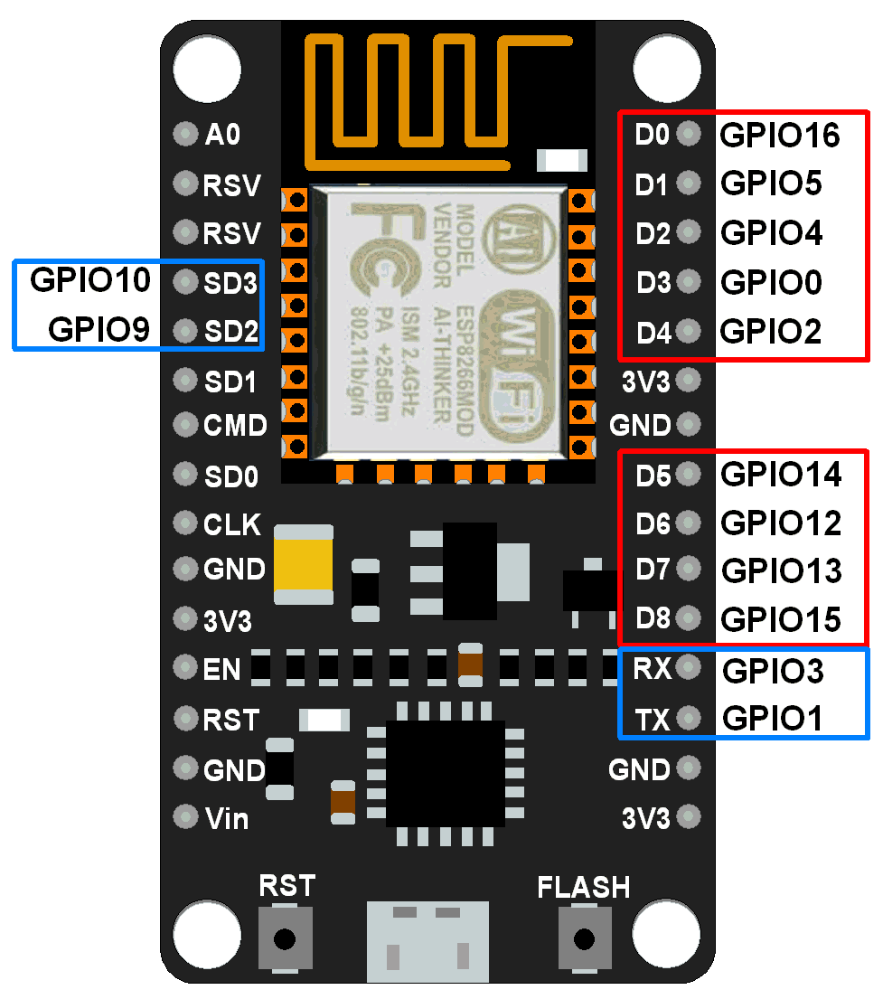
We are going to program nodemcu there is a seperate ide but in this project we are programing it using arduino ide, hence the ide thinks that we are programing for arduino so  before programming we have to know about the pinouts of nodemcu corresponding to arduino.Below is the image through which you can understand the pinout .

Eg: If we use D0 pin of Nodemcu as output ,we have to declare pin 16 as an output in arduino ide.

After knowing the pinouts now let us jump in to the hardware and coding section .

HARDWARE:

Things needed:


  • 1 x  Nodemcu
  • 1 x  L298N motor driver
  • 2 x Bo motors
  • 3 x wheels
  • jumper wires
NODEMCU:
L298N MOTORDRIVER:


BO MOTORS:
JUMPER WIRES:


Now its time to connect all these connections :

 Description 

Picture of Descritions
Getting to Know Your L298N Dual H-Bridge Motor Controller Module
An H-Bridge is a circuit that can drive a current in either polarity and be controlled by Pulse Width Modulation (PWM).
What is Pulse Width Modulation?
Pulse Width Modulation is a means in controlling the duration of an electronic pulse. Motors will last much longer and be more reliable if controlled through PWM.
Specifications:
  • Double H bridge Driver Chip: L298N
  • Logical voltage: 5V
  • Drive voltage: 5V-35V
  • Logical current: 0-36mA
  • Drive current: 2A (MAX single bridge)
  • Max power: 25W
Note: Built-in 5v power supply, when the driving voltage is 7v-35v. But i recommend you not to power up your microcontroller with on-board 5v power supply.
1:connect the bo motor to the motor driver as shown below

2: connect the motor driver to nodemcu as given below:
  • GPIO2(D4)- IN3
  • GPIO15(D8)-IN1
  • GPIO0(D3)-IN4
  • GPIO13(D7)-IN2
  • GPIO14(D5)-Enb-A
  • GPIO12(D6)-Enb-B
3:Supply Connections :
+12v Positive terminal of the battery to be connected.
GND Ground terminal of the battery to be connected.
+5v +5v input (unnecessary if your power source is less than +7v to +9v, if the power source is greater than +9v to +35v then it can act as a 5v out)
Input Connections :
(Motor A)
ENA - Enables PWM signal for Motor A
IN1 - Enable Motor A
IN2 - Enable Motor A
(Motor B)
ENB - Enables PWM signal for Motor B
IN3: Enable Motor B
IN4: Enable Motor B
Note :
  • Make sure you have all of your grounds connected together. (NodeMCUPower Source, and Motor Driver)
  • The PWM Pins are unnecessary if you do not want to control PWM features.
Software Requirements
  • Arduino IDE
  • The code is given below just paste the code in the arduino ide :
  • select the nodemcu board and the correct com port 

        Click here to download the Ardunio code file directly
                                    

CODE:


#include <ESP8266WiFi.h>

#include <BlynkSimpleEsp8266.h>

/* define L298N or L293D motor control pins */
int leftMotorForward = 2;     /* GPIO2(D4) -> IN3   */
int rightMotorForward = 15;   /* GPIO15(D8) -> IN1  */
int leftMotorBackward = 0;    /* GPIO0(D3) -> IN4   */
int rightMotorBackward = 13;  /* GPIO13(D7) -> IN2  */
int z;

/* define L298N or L293D enable pins */
int rightMotorENB = 14; /* GPIO14(D5) -> Motor-A Enable */
int leftMotorENB = 12;  /* GPIO12(D6) -> Motor-B Enable */

// You should get Auth Token in the Blynk App.
// Go to the Project Settings (nut icon).
// Use your own WiFi settings
char auth[] = "**********";
char ssid[] = "type your network name here ";
char pass[] = "type your network password here";
// neutral zone settings for x and y
// joystick must move outside these boundary numbers to activate the motors
// makes it a little easier to control the wifi car
int minRange = 312;
int maxRange = 712;
// analog speeds from 0 (lowest) - 1023 (highest)
// 3 speeds used -- 0 (noSpeed), 350 (minSpeed), 850 (maxSpeed).
// use whatever speeds you want...too fast made it a pain in the ass to control
int minSpeed = 450;
int maxSpeed = 1023;
int noSpeed = 0;
void moveControl(int x, int y)
{
  // movement logic
  // move forward

   // y je vetsi jak maxrange a současně x je vetsi jak minRange a současne mensi jak max range 
  if(y >= maxRange && x >= minRange && x <= maxRange) //zataci R
  {
  analogWrite(leftMotorENB,z);
analogWrite(rightMotorENB,z);  

  digitalWrite(leftMotorForward,HIGH);
  digitalWrite(rightMotorForward,HIGH);
  digitalWrite(leftMotorBackward,LOW);
  digitalWrite(rightMotorBackward,LOW);
  }
 //MOVE FORWARD RIGHT
  else if(x <= minRange && y >= maxRange )
  {
  digitalWrite(leftMotorENB,maxSpeed);
  digitalWrite(rightMotorENB,minSpeed); 
  digitalWrite(leftMotorForward,HIGH);
  digitalWrite(rightMotorForward,HIGH);
  digitalWrite(rightMotorBackward,LOW);
  digitalWrite(leftMotorBackward,LOW);  
}
  
  // move  right
  else if(x >= maxRange && y >= minRange && y<=maxRange)   //zataci R
  { analogWrite(leftMotorENB,z);
analogWrite(rightMotorENB,z);  
  digitalWrite(leftMotorForward,HIGH);
  digitalWrite(rightMotorForward,LOW);
  digitalWrite(rightMotorBackward,HIGH);
  digitalWrite(leftMotorBackward,LOW);
  }

  // move forward LEFT
  
  else if(x <= minRange && y >= maxRange )
  {
  digitalWrite(leftMotorENB,minSpeed);
  digitalWrite(rightMotorENB,maxSpeed); 
  digitalWrite(leftMotorForward,HIGH);
  digitalWrite(rightMotorForward,HIGH);
  digitalWrite(rightMotorBackward,LOW);
  digitalWrite(leftMotorBackward,LOW);  
}
  // moveleft
  else if(x <= minRange && y >= minRange && y <= maxRange)
  {
   analogWrite(leftMotorENB,z);
analogWrite(rightMotorENB,z);   
  digitalWrite(leftMotorForward,LOW);
  digitalWrite(rightMotorForward,HIGH);
  digitalWrite(rightMotorBackward,LOW);
  digitalWrite(leftMotorBackward,HIGH);  
}
  // neutral zone
  else if(y < maxRange && y > minRange && x < maxRange && x > minRange)
  {
  digitalWrite(leftMotorENB,LOW);
  digitalWrite(rightMotorENB,LOW);
  digitalWrite(leftMotorForward,LOW);
  digitalWrite(leftMotorBackward,LOW);
  digitalWrite(rightMotorForward,LOW);
  digitalWrite(rightMotorBackward,LOW);
  }
 // move back
  else if(y <= minRange && x >= minRange && x <= maxRange)
  {
    analogWrite(leftMotorENB,z);
analogWrite(rightMotorENB,z);  
  digitalWrite(leftMotorBackward,HIGH);
  digitalWrite(rightMotorBackward,HIGH);
  digitalWrite(leftMotorForward,LOW);
  digitalWrite(rightMotorForward,LOW);
  }
  // move back and right
 else if(y <= minRange && x <= minRange)
  {
  digitalWrite(leftMotorENB,maxSpeed);
  digitalWrite(rightMotorENB,minSpeed); 
  digitalWrite(leftMotorForward,LOW);
  digitalWrite(rightMotorForward,LOW);
  digitalWrite(rightMotorBackward,HIGH);
  digitalWrite(leftMotorBackward,HIGH);  
  }
  // move back and left
  else if(y <= minRange && x >= maxRange)
 {
 digitalWrite(leftMotorENB,minSpeed);
  digitalWrite(rightMotorENB,maxSpeed); 
  digitalWrite(leftMotorForward,LOW);
  digitalWrite(rightMotorForward,LOW);
  digitalWrite(rightMotorBackward,HIGH);
  digitalWrite(leftMotorBackward,HIGH);  
  }
}

void setup()
{
  // initial settings for motors off and direction forward
  pinMode(leftMotorForward, OUTPUT);
  pinMode(rightMotorForward, OUTPUT); 
  pinMode(leftMotorBackward, OUTPUT);  
  pinMode(rightMotorBackward, OUTPUT);

  /* initialize motor enable pins as output */
  pinMode(leftMotorENB, OUTPUT); 
  pinMode(rightMotorENB, OUTPUT);


  Blynk.begin(auth, ssid, pass);
 }
void loop()
{
  

  Blynk.run();
}
BLYNK_WRITE(V1)

{
    
  int x = param[0].asInt();
  int y = param[1].asInt();
  
  moveControl(x,y); 
 }

BLYNK_WRITE(V2)

{
    
  z = param[0].asInt();
}


SETTING BLYNK APP :
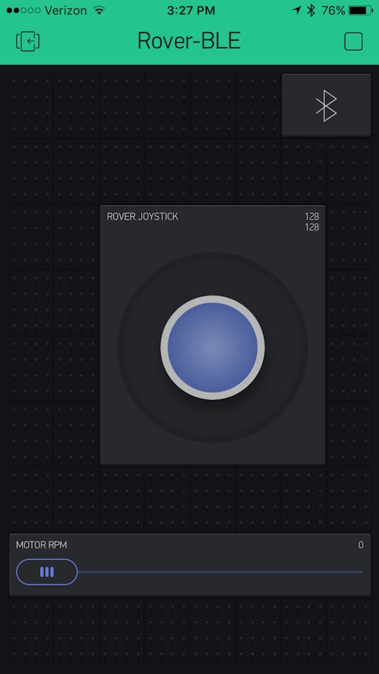
Picture of ​BLYNK App Setup on Phone

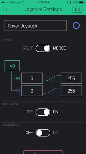
Blynk Joystick Setup
Change  the pin to V1 and value from 0 to 1023 in both the cases.
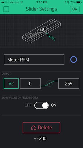
Blynk Motor speed adjustment slider switch set-up
Change  the pin to V2 and value from 0 to 1023 .


Thats it the project is complete you can now control the car using blynk joystick.

  • Turn on your mobile hotspot, wait till the nodemcu connects to the mobile hotspot and ""walla! "now you can control the car using your mobile via blynk .


Sunday, June 9, 2019

How to program Esp8266 Esp-01 using Arduino Uno

Hey guys,

Today we are going to learn about how to program your Esp8266 Esp01 wifi module using arduino uno.
Programming ESP8266 ESP-01 with Arduino


COMPONENTS AND SUPPLIES

A000066 iso both
Arduino UNO & Genuino UNO
×1
On semiconductor lm317tg
Linear Regulator with Adjustable Output
×1
Mfr 25fbf52 475r sml
Resistor 475 ohm
×1
09590 01
LED (generic)
×1
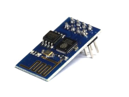
Esp01
ESP8266 ESP-01
×1

ABOUT THIS PROJECT

ESP8266 module is of low cost and comes pre-programmed with an AT command set firmware, meaning, you can simply hook this up to your Arduino device and get about as much WiFi-ability as a WiFi Shield offers.This module has a powerful on-board processing and storage capability that allows it to be integrated with the sensors and other application through its GPIOs .
In this tutorial we can see how to get started with the ESP-01 Wi-Fi module  and verify that there is communication established between the  wifi module and your computer.


STEP 1 : SETTING UP THE ARDUINO

First download Arduino IDE ensure that you have the latest software version , visit the following URL: https://www.arduino.cc/en/Main/Software.  to download latest arduino ide.
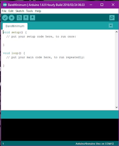
Upload Bareminimum sketch from examples to arduino this is to make sure that there are no other programs running on arduino and using serial communication channel.Serial communication window (Serial monitor)can opened by clicking a small icon present in the right most corner of your arduino ide .
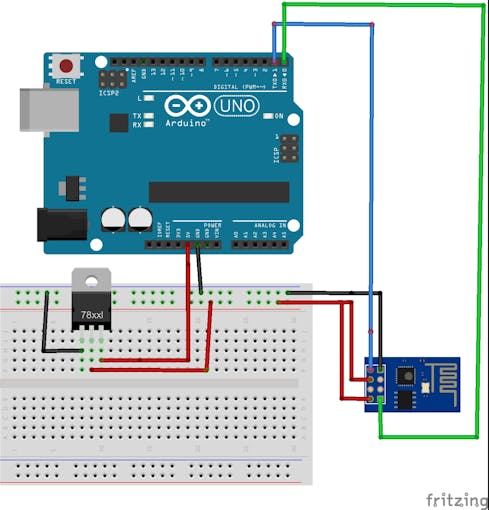
AT firmware is compatible with the Arduino IDE, so we are going to use this firmware for this tutorial . Connect ESP8266 as per the above circuit.
  • VCC shall be connected to the 3.3V power supply.
  • GPIO0 and GPIO2 are general purpose digital ports. GPIO0 also controls the module mode (programming or normal operation). In our case (normal operation), it shall be connected to 3.3V (high). GPIO2 is not used in this example.
  • Rx: Goes to Arduino pin0(Rx) .
  • CH_PD: Chip enable. Keep it on high (3.3V) for normal operation.
  • RST: Reset. Keep it on high (3.3V) for normal operation. Put it on 0V to reset the chip.(not using this pin in the project)
  • GND is ground.
  • Tx: Goes to Arduino pin1(Tx).


Setup continued

Open  the serial monitor change the baud rate to 115200 and coose NL and CR (new line and carrage return) it is available at the bottom of serial monitor.Type AT on the serial monitor and enter on the send button ,you will see an OK response .If you see garbage value on the screen, try resetting the module, or checking your baud rate. Make sure the NL and CR option is set.


STEP 2: Installing ESP8266 Platform

First arduino environment has to be setup to make it compactable with the ESP module. It is required to have Arduino version 1.6.4 or higher in order to be able to install the ESP’s platform packages.The latest available version of arduino is 1.8.9 
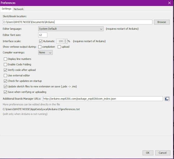
1.Go to file and open the preferences or press Ctrl+Comma.

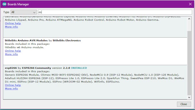
2. Enter http://arduino.esp8266.com/stable/package_esp8266com_index.jsoninto Additional Board Manager URLs field and click the “OK” button
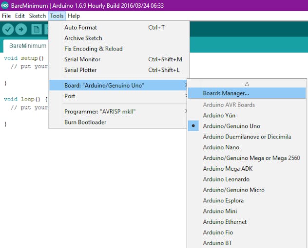
3. Open boards manager. Go to Tools > Board > Boards Manager…
4. Scroll down, select the ESP8266 board menu and install “ESP8266 platform”
5.Choose your ESP8266 board from Tools > Board > Generic ESP8266 Module.

STEP 3. Controlling Input and Output

In Arduino IDE go to examples and take blink sketch, change the pin no to from 13 since there is only two gpio pins for ESP8266 (GPIO0 and GPIO2).
NOTe: Plz  Make sure that GPIO 0 is grounded while uploading the code.
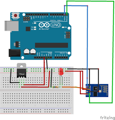
Note: Connect the reset pin of the arduino to the ground (GND).By doing this we are telling the arduino that we are not  uploading the sketch to ardiuno instead we are uploading the code to esp8266 module.(If u do not connect the arduino to the groud the code will get uploaded to arduino Atmega chipclick here to see the whole process in the form of vedio instead of esp8266 module.)
Connect the ESP as per the image and upload the sketch 
void setup() {  // initialize digital esp8266 gpio 2 as an output.
  pinMode(2, OUTPUT);
}

// the loop function runs over and over again forever
void loop() {
  digitalWrite(2, HIGH);   // turn the LED on (HIGH is the voltage level)
  delay(1000);              // wait for a second
  digitalWrite(2, LOW);    // turn the LED off by making the voltage LOW
  delay(1000);              // wait for a second
}
while uploading the sketch the compiler colour changes to orange .This shows that the sketch is being uploaded to the wifi module ,wait till the compiler shows 100% and see the magic.

Click here to download complete Datasheet of esp8266(https://bi-t.xyz/YT7H7Mi)

Click here to watch how to program esp8266 using arduino : (https://www.youtube.com/watch?v=N5MoXarCF_4)
In  the future projects i'm going to tell you guys how to control esp8266 module using your smartphone so stay tuned until we meet next time : )
All the best future engineering Inventors :)