Hey guys,
Today we are going to learn about how to program your Esp8266 Esp01 wifi module using arduino uno.

Today we are going to learn about how to program your Esp8266 Esp01 wifi module using arduino uno.
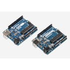
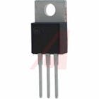
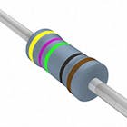
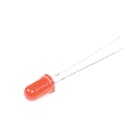
COMPONENTS AND SUPPLIES
 |
| × | 1 | |||
 |
| × | 1 | |||
 |
| × | 1 | |||
 |
| × | 1 | |||
 |
| × | 1 |
ABOUT THIS PROJECT
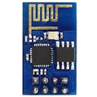
ESP8266 module is of low cost and comes pre-programmed with an AT command set firmware, meaning, you can simply hook this up to your Arduino device and get about as much WiFi-ability as a WiFi Shield offers.This module has a powerful on-board processing and storage capability that allows it to be integrated with the sensors and other application through its GPIOs .
In this tutorial we can see how to get started with the ESP-01 Wi-Fi module and verify that there is communication established between the wifi module and your computer.
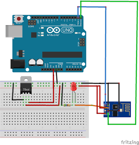
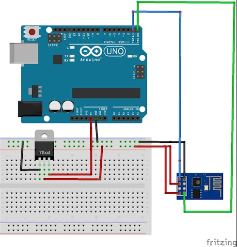 |
| Pinout connection diagram. |
STEP 1 : SETTING UP THE ARDUINO
First download Arduino IDE ensure that you have the latest software version , visit the following URL: https://www.arduino.cc/en/Main/Software. to download latest arduino ide.
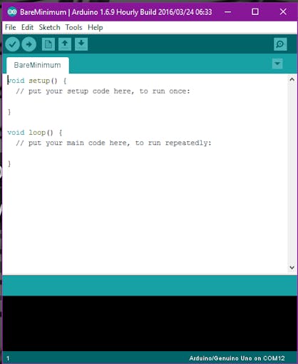
Upload Bareminimum sketch from examples to arduino this is to make sure that there are no other programs running on arduino and using serial communication channel.Serial communication window (Serial monitor)can opened by clicking a small icon present in the right most corner of your arduino ide .
AT firmware is compatible with the Arduino IDE, so we are going to use this firmware for this tutorial . Connect ESP8266 as per the above circuit.
- VCC shall be connected to the 3.3V power supply.
- GPIO0 and GPIO2 are general purpose digital ports. GPIO0 also controls the module mode (programming or normal operation). In our case (normal operation), it shall be connected to 3.3V (high). GPIO2 is not used in this example.
- Rx: Goes to Arduino pin0(Rx) .
- CH_PD: Chip enable. Keep it on high (3.3V) for normal operation.
- RST: Reset. Keep it on high (3.3V) for normal operation. Put it on 0V to reset the chip.(not using this pin in the project)
- GND is ground.
- Tx: Goes to Arduino pin1(Tx).
Setup continued
Open the serial monitor change the baud rate to 115200 and coose NL and CR (new line and carrage return) it is available at the bottom of serial monitor.Type AT on the serial monitor and enter on the send button ,you will see an OK response .If you see garbage value on the screen, try resetting the module, or checking your baud rate. Make sure the NL and CR option is set.
STEP 2: Installing ESP8266 Platform
First arduino environment has to be setup to make it compactable with the ESP module. It is required to have Arduino version 1.6.4 or higher in order to be able to install the ESP’s platform packages.The latest available version of arduino is 1.8.9
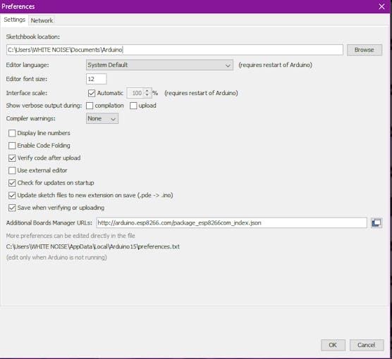
1.Go to file and open the preferences or press Ctrl+Comma.

2. Enter http://arduino.esp8266.com/stable/package_esp8266com_index.jsoninto Additional Board Manager URLs field and click the “OK” button
3. Open boards manager. Go to Tools > Board > Boards Manager…
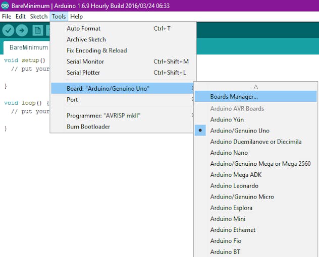
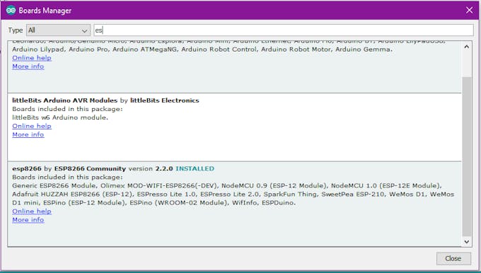
4. Scroll down, select the ESP8266 board menu and install “ESP8266 platform”
5.Choose your ESP8266 board from Tools > Board > Generic ESP8266 Module.

STEP 3. Controlling Input and Output
In Arduino IDE go to examples and take blink sketch, change the pin no to 2 from 13 since there is only two gpio pins for ESP8266 (GPIO0 and GPIO2).
NOTe: Plz Make sure that GPIO 0 is grounded while uploading the code.
Note: Connect the reset pin of the arduino to the ground (GND).By doing this we are telling the arduino that we are not uploading the sketch to ardiuno instead we are uploading the code to esp8266 module.(If u do not connect the arduino to the groud the code will get uploaded to arduino Atmega chipclick here to see the whole process in the form of vedio instead of esp8266 module.)
Connect the ESP as per the image and upload the sketch
void setup() {  // initialize digital esp8266 gpio 2 as an output.
  pinMode(2, OUTPUT);
}

// the loop function runs over and over again forever
void loop() {
  digitalWrite(2, HIGH);   // turn the LED on (HIGH is the voltage level)
  delay(1000);              // wait for a second
  digitalWrite(2, LOW);    // turn the LED off by making the voltage LOW
  delay(1000);              // wait for a second
}
while uploading the sketch the compiler colour changes to orange .This shows that the sketch is being uploaded to the wifi module ,wait till the compiler shows 100% and see the magic.
Click here to watch how to program esp8266 using arduino : (https://www.youtube.com/watch?v=N5MoXarCF_4)
Click here to watch how to program esp8266 using arduino : (https://www.youtube.com/watch?v=N5MoXarCF_4)
In the future projects i'm going to tell you guys how to control esp8266 module using your smartphone so stay tuned until we meet next time : )
All the best future engineering Inventors :)
No comments:
Post a Comment